What Industrial Cooling Tower Fans Actually Do — and Why They Matter
Industrial cooling tower fans are the primary air-moving components inside wet and dry cooling towers, responsible for drawing or forcing large volumes of ambient air through the heat exchange media to carry heat away from process water or refrigerant circuits. Without the fan, the cooling tower becomes a passive evaporative structure with dramatically reduced heat rejection capacity — completely insufficient for the thermal loads generated by power plants, chemical refineries, data centers, HVAC chillers, and heavy manufacturing processes.
The fan's job sounds straightforward: move air. But in a cooling tower environment, that job is performed under conditions that stress components far more than in most industrial fan applications. The fan operates in a saturated, highly humid airstream at or near 100% relative humidity, often exposed to chemical water treatment compounds carried over as mist, varying ambient temperatures from freezing winters to peak summer heat, and continuous duty cycles measured in thousands of hours per year. A cooling tower fan that fails or loses efficiency does not just inconvenience operations — in process industries, it can trigger an unplanned thermal shutdown of the entire facility it serves.
Understanding how these fans are designed, what differentiates a high-performance unit from a marginal one, and how to maintain them properly is practical knowledge that directly affects energy costs, equipment reliability, and total cost of ownership for any facility operating a mechanical-draft cooling tower.
Axial vs. Centrifugal: The Two Fan Types Used in Cooling Towers
The large majority of industrial cooling towers use axial-flow fans — propeller-style fans where the airflow moves parallel to the fan shaft axis. A smaller subset of tower designs, particularly forced-draft configurations in compact or indoor installations, use centrifugal fans where air enters axially and is discharged radially at higher static pressure. Each type has defined strengths and limitations that make it appropriate for specific tower designs and operating conditions.
Axial Cooling Tower Fans
Axial fans dominate induced-draft and propeller-type forced-draft cooling towers because they move very large volumes of air at relatively low static pressure with high efficiency. A single large-diameter axial fan — commonly ranging from 1.2 meters to over 12 meters in diameter in industrial applications — can handle airflow rates of tens of thousands of cubic meters per hour. Their large diameter allows them to operate at low rotational speeds (typically 80–350 RPM for large units), which reduces noise, mechanical stress, and drive component wear. The slow tip speed also minimizes blade erosion from water droplet impact, a persistent challenge in the high-humidity cooling tower environment.
Adjustable-pitch axial fans are particularly valuable in cooling tower service. By varying the blade pitch angle — either manually during a scheduled shutdown or automatically during operation via pneumatic or electric actuators — the fan's airflow output can be tuned to match the actual thermal load without changing motor speed or installing variable frequency drives. This capability is central to energy optimization in large cooling tower installations where the thermal load varies seasonally and diurnally.
Centrifugal Cooling Tower Fans
Centrifugal fans are used in forced-draft cooling towers where ducted airflow distribution, higher static pressure capability, or indoor installation constraints make axial fans impractical. They are inherently better suited to systems with significant duct resistance downstream of the fan, and their enclosed impeller design is more tolerant of airstream contamination and debris ingestion than open-blade axial fans. The trade-off is that centrifugal fans are generally less efficient than axial fans at the low-pressure, high-volume operating point characteristic of most cooling towers, and they are physically larger and heavier for a given airflow rate.
Fan Blade Materials: FRP, Aluminum, and Stainless Steel Compared
The blade material used in a cooling tower fan has a direct impact on corrosion resistance, weight, structural fatigue life, repairability, and overall system cost. The cooling tower environment — warm, humid, chemically treated water mist, and frequent thermal cycling — is one of the most corrosive environments any fan blade will encounter in industrial service. Selecting the wrong material leads to premature blade failure, potentially catastrophic if a blade separates from the hub at operating speed.
| Blade Material |
Corrosion Resistance |
Weight |
Fatigue Life |
Typical Application |
| FRP (Fiberglass Reinforced Plastic) |
Excellent |
Light |
Very High |
Most industrial cooling towers; chemical and power plants |
| Aluminum Alloy |
Good (anodized) |
Light |
High |
HVAC cooling towers; moderate-duty applications |
| Stainless Steel (316L) |
Superior |
Heavy |
Very High |
Aggressive chemical environments; seawater-cooled systems |
| Carbon Fiber Composite |
Excellent |
Very Light |
Exceptional |
Large-diameter high-performance fans; offshore and power generation |
Comparison of cooling tower fan blade materials by key performance and application characteristics
FRP blades are the industry standard for the majority of industrial cooling tower applications. The glass-fiber reinforcement embedded in a polyester or epoxy resin matrix produces a blade that is light, stiff, corrosion-immune to virtually all cooling water chemistries, and manufacturable in optimized aerodynamic profiles. FRP blades are also field-repairable — minor surface damage from hail, debris, or erosion can be patched with resin and glass cloth to restore structural integrity and aerodynamic smoothness without full blade replacement.
Aluminum blades remain common in HVAC-scale cooling towers and moderate-duty industrial applications where capital cost is a primary constraint. They require anodizing or protective coating to resist the alkaline or mildly acidic water treatment compounds used in most cooling systems. In high-chloride environments — coastal installations, systems using seawater as makeup water, or towers near chlorination dosing points — aluminum is vulnerable to pitting corrosion and should be avoided in favor of FRP or stainless steel.
Drive Systems: Gear Reducers, Belt Drives, and Direct-Drive Configurations
Cooling tower fans turn slowly relative to standard motor speeds — large-diameter axial fans typically need to spin at 80–200 RPM while the drive motor runs at 960–1,480 RPM (for 4- or 6-pole motors on 50Hz supply) or up to 1,750 RPM on 60Hz systems. A speed-reduction drive system bridges this gap. The three principal configurations used in industrial cooling towers each carry distinct advantages, maintenance requirements, and failure modes.
Right-Angle Gear Reducers
The right-angle gear reducer — typically a spiral bevel or bevel-helical gearbox — is the traditional and most widely deployed drive system in large induced-draft cooling towers. The motor sits horizontally on a drive deck above the fan stack, and the gearbox turns the drive shaft 90 degrees to connect to the vertically oriented fan shaft. Purpose-built cooling tower gearboxes are designed for continuous immersion in a humid environment and are splash-lubricated with oil. Their primary maintenance requirements are periodic oil changes (typically every 8,000–10,000 operating hours or annually), oil level checks, and vibration monitoring to detect developing gear or bearing wear. Properly maintained gear reducers have service lives exceeding 20 years in cooling tower service.
Belt Drive Systems
V-belt and synchronous belt drives are common on small to medium cooling towers, particularly in HVAC and light-industrial package tower units. The motor and fan shaft are positioned with parallel axes, connected by a belt running over sheaves or sprockets. Belt drives offer simple installation, lower initial cost than gear reducers, and easy speed adjustment by changing sheave sizes. The limitations are more significant in continuous-duty industrial service: belts stretch and wear over time and require periodic tensioning and replacement, typically every 2,000–8,000 hours depending on load and temperature. In the humid cooling tower environment, belt degradation can be accelerated by moisture exposure and the ozone generated near some electrical equipment. Synchronous (toothed) belts perform better than V-belts in this context due to their positive engagement and lower maintenance sensitivity to tension variation.
Direct-Drive and Permanent Magnet Motor Systems
Direct-drive cooling tower fans eliminate the intermediate gearbox or belt entirely by using a low-speed motor — commonly a permanent magnet synchronous motor (PMSM) or a large-frame induction motor with high pole count — connected directly to the fan hub. This configuration removes the most maintenance-intensive component from the drivetrain and eliminates oil leakage risk entirely, which is particularly valuable in installations near water supplies or where lubricant contamination is an environmental concern. Direct-drive systems paired with variable frequency drives (VFDs) offer the most precise and energy-efficient speed control available, capable of continuously adjusting fan speed across a wide range to match thermal load with minimal energy waste. The higher upfront cost of direct-drive systems is generally recovered within 3–5 years through reduced maintenance costs and improved energy efficiency at part-load operating conditions.

Energy Efficiency: How Fan Design and Speed Control Cut Operating Costs
Cooling tower fans are among the largest electrical consumers in industrial facilities that rely on process cooling. A single large cooling tower fan motor may draw 75–750 kW, and a facility with multiple cells running continuously represents a substantial portion of the site's electricity bill. Improving the aerodynamic efficiency of the fan itself and implementing intelligent speed control are the two highest-leverage strategies for reducing this cost without sacrificing cooling performance.
Aerodynamic Blade Profile Optimization
Modern high-efficiency cooling tower fan blades use airfoil cross-sections derived from aerospace research — typically cambered profiles with carefully optimized chord length, twist distribution along the blade span, and leading-edge geometry. These profiles generate more lift (airflow) per unit of drag (power consumed) than older flat or simply curved blades still found on many aging towers. Retrofitting a tower with aerodynamically optimized FRP blades can reduce fan power consumption by 15–30% at the same airflow output, which translates directly into reduced electricity costs and lower motor and gearbox loading. Several manufacturers offer blade retrofit programs specifically sized for standard cooling tower fan stacks, making upgrades achievable without structural modifications to the tower.
Variable Frequency Drives and the Fan Affinity Laws
The fan affinity laws describe the relationship between fan speed and power consumption: power varies as the cube of speed. This means reducing a fan's speed to 80% of full speed reduces power consumption to approximately 51% (0.8³ = 0.512). Running at 70% speed consumes only 34% of full-speed power. In cooling towers, where the required airflow decreases significantly during cooler ambient conditions, nighttime operation, or reduced process load, VFD-controlled fans produce dramatic energy savings. A tower that runs at full speed for only half the year and at 70% speed for the other half will save approximately 33% of annual fan energy compared to running at full speed year-round — a substantial return on the VFD investment in high-operating-hour applications.
Fan Cylinder and Inlet Bell Geometry
The aerodynamic performance of a cooling tower fan is not determined by the blade alone — the fan cylinder (stack casing) and inlet bell geometry have a significant effect on efficiency. A properly designed inlet bell creates a smooth, accelerating airflow into the fan disk with minimal turbulence and separation losses. The tip clearance between blade tip and fan cylinder wall is equally critical: excessive clearance allows recirculation of air from the high-pressure discharge side back to the low-pressure inlet side, reducing effective airflow without reducing power consumption. Industry best practice targets tip clearances of 0.1–0.5% of fan diameter, which for a 6-meter diameter fan translates to approximately 6–30mm. Maintaining this clearance over the fan's service life requires periodic inspection and correction of any distortion in the fan cylinder caused by thermal cycling, corrosion, or structural settlement.
Maintenance Practices That Prevent Cooling Tower Fan Failures
Cooling tower fans operate in a demanding environment, but the majority of failures are preventable with structured inspection and maintenance programs. The consequences of unplanned fan failure range from reduced cooling capacity and process upsets to catastrophic structural failure if a blade or hub component fails at operating speed. A proactive maintenance approach is not just about reducing costs — it is an operational safety requirement.
Vibration Monitoring and Balance Checks
Vibration is the most reliable early indicator of developing mechanical problems in a cooling tower fan assembly. Unbalance — caused by blade erosion, debris accumulation on one blade, or a previous repair that altered blade mass — produces a vibration signature at the fan's rotational frequency. Bearing deterioration produces higher-frequency vibration signatures identifiable through vibration spectrum analysis. Most modern cooling tower installations include vibration switches that trigger an automatic shutdown if vibration exceeds a preset threshold, preventing catastrophic failure. However, vibration switches provide only a gross protection — a scheduled vibration measurement program using a portable analyzer, conducted quarterly or semi-annually, identifies developing problems at a much earlier stage when corrective action is simpler and less costly.
Blade Inspection and Surface Condition Assessment
FRP blades should be visually inspected at every scheduled maintenance outage — typically at least annually and after any severe weather event. Inspection focuses on the leading edge (most vulnerable to erosion and impact damage), blade root attachment hardware (bolts, clamps, and root inserts), and the blade surface for delamination, cracking, or blistering. Small surface erosion on the leading edge significantly reduces aerodynamic efficiency and should be repaired with epoxy filler and re-coating rather than left to progress. Any blade showing through-thickness cracking, root insert loosening, or significant delamination must be removed from service immediately — these conditions indicate imminent structural failure risk.
Routine Maintenance Checklist for Cooling Tower Fan Systems
- Monthly: Check gearbox oil level; inspect for external oil leaks; confirm vibration switch set points are active; clear debris from fan inlet and fill deck.
- Quarterly: Take vibration measurements on gearbox and motor bearings; inspect belt tension and condition (belt-drive systems); check blade pitch setting consistency across all blades.
- Annually (or at scheduled outage): Full blade visual inspection and surface repair; check all blade root hardware torque to specification; inspect fan hub for corrosion or cracking; measure tip clearance; change gearbox oil; inspect and re-grease shaft couplings and drive shaft bearings; check motor insulation resistance and terminal condition.
- Every 3–5 years: Full fan assembly balance check; gearbox internal inspection (gear tooth condition, bearing clearances); non-destructive testing (NDT) of FRP blades and hub components in high-cycle or chemically aggressive service.
Cold Weather Operation and Icing Prevention
Cooling towers operating in cold climates face the additional challenge of ice formation on fan blades, inlet louvers, and fill media during winter operation. Ice accumulation on fan blades causes severe imbalance — even a modest ice build-up of 2–5 kg asymmetrically distributed across the blade set produces vibration loads that can damage gearbox bearings and fan hub components within minutes of operation. Many facilities address this through automatic fan reversal cycles that periodically blow warm discharge air downward over the inlet, melting accumulated ice. Variable speed operation is also effective: reducing fan speed during icing conditions maintains some air movement for heat rejection while minimizing the kinetic energy stored in ice-laden rotating components. Always verify that gearbox oil is specified for low-temperature operation at the site's winter extremes — standard gear oils can become too viscous to lubricate adequately below −10°C, and synthetic low-temperature oils are required for colder sites.
Selecting the Right Industrial Cooling Tower Fan: Key Parameters to Specify
When sourcing a replacement or new cooling tower fan — whether for a new tower installation or a retrofit of an aging system — specifying the correct parameters upfront prevents costly mismatches and ensures the fan delivers the required thermal performance at acceptable energy and noise levels.
- Fan diameter and tip clearance: The fan must fit the existing or planned fan stack diameter with the correct tip clearance for aerodynamic efficiency. Measure the internal diameter of the fan cylinder accurately — variations of even 25mm matter at large diameters.
- Required airflow (m³/s or CFM) and static pressure: Determine the design airflow from the tower's thermal rating and the static pressure resistance of the fill, drift eliminators, and air inlet path. These two values define the fan's operating point and must match the selected fan's performance curve.
- Number of blades and pitch range: More blades generally produce higher airflow at a given speed but with greater solidity and potentially higher noise. Variable-pitch fans require specifying the operating pitch range and whether manual or auto-pitch adjustment is needed.
- Hub material and corrosion protection: The hub is the structurally critical component. Specify hot-dip galvanized steel, FRP, or stainless steel based on the water chemistry and environmental conditions at the site.
- Noise level requirements: Cooling tower fan noise is regulated by local ordinances at many industrial and commercial sites. Obtain octave-band sound power level data from the manufacturer and verify compliance with site requirements before ordering.
- Drive interface compatibility: Confirm the fan hub bore, keyway, and flange dimensions are compatible with the existing or planned drive shaft and gearbox output flange. Dimensional mismatches in cooling tower fan hubs are a common and expensive procurement error.
Engaging the fan manufacturer's engineering team with complete tower operating data — including design dry-bulb and wet-bulb temperatures, process heat load, water flow rate, and tower cell dimensions — allows them to generate a fan performance guarantee backed by computational fluid dynamics (CFD) analysis and test data. For large or critical installations, this level of engineering validation is a worthwhile investment that eliminates performance uncertainty before the equipment ships.


 Eng
Eng English
 中文简体
中文简体
 What Is an Open Circuit Cooling Tower and How Does It Work?
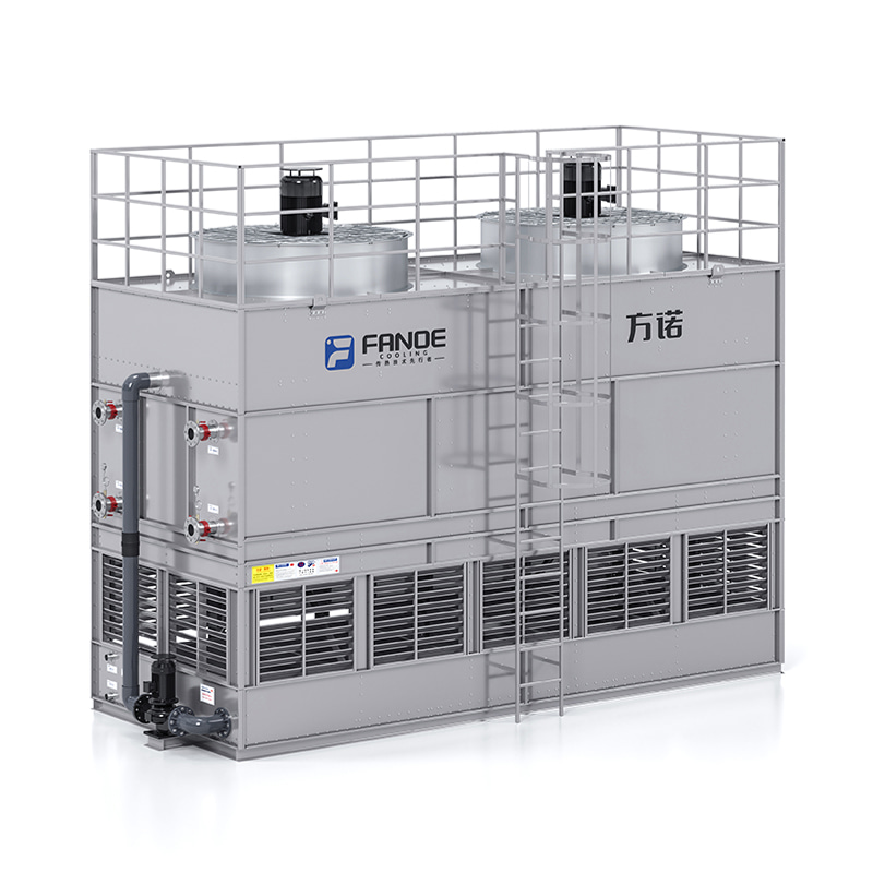 What Is a Closed Type Cooling Tower and When Should You Use One?How a Closed Type Cooling Tower Actually Works A closed type cooling tower — also widely referred to as a closed-circuit cooling tower, closed-loop c...
 Cooling Tower Guide: Types, How They Work & Selection CriteriaHow a Cooling Tower Actually Works A cooling tower is a heat rejection device that removes waste heat from a process or building system by transferrin...
 Industrial Cooling Towers: How They Work, Types, and How to Keep Them Running RightWhat Industrial Cooling Towers Do and Why They Matter Industrial cooling towers are large heat rejection systems designed to remove excess thermal en...
 Evaporative Condenser Explained: How It Works, How to Choose One, and How to Keep It RunningWhat Is an Evaporative Condenser and How Does It Work? An evaporative condenser is a heat rejection device that combines the functions of a condenser ...