How a Closed Type Cooling Tower Actually Works
A closed type cooling tower — also widely referred to as a closed-circuit cooling tower, closed-loop cooling tower, or fluid cooler — rejects heat from a process fluid without ever allowing that fluid to come into direct contact with the outside air or the spray water used for cooling. This fundamental separation is what distinguishes it from a conventional open cooling tower, and it is the source of nearly every practical advantage the closed design offers.
Inside a closed-circuit cooling tower, the hot process fluid (typically water or a water-glycol mixture) circulates through a sealed coil or tube bundle located within the tower structure. This is the primary circuit — it is completely isolated from the outside environment. Simultaneously, a secondary circuit pumps spray water (sometimes called the sump water or recirculating water) over the exterior surface of those coils from above. Fans draw air through the tower, and the combination of air movement and evaporation of the spray water removes heat from the coil surfaces, cooling the process fluid inside. The process fluid never touches the spray water, never touches the air, and never leaves the sealed loop. The heat transfer happens entirely across the coil wall — a metal barrier separating the two circuits.
In some configurations, particularly in cooler ambient conditions, closed type cooling towers can also operate in a dry mode — shutting off the spray water and relying entirely on sensible heat transfer from the coil surface to the moving air. This hybrid capability allows operators to reduce water consumption significantly during periods when ambient temperatures are low enough that evaporative cooling isn't needed to meet the required process outlet temperature.
Closed Type vs Open Type Cooling Tower: The Real Differences
The comparison between closed and open cooling towers comes down to more than a simple design preference — it involves fundamentally different trade-offs in contamination risk, maintenance complexity, water consumption, equipment longevity, and total cost of ownership. Understanding these differences in specific terms is what allows engineers and facility managers to make the correct selection for a given application.
Direct comparison: closed type vs open type cooling tower
| Characteristic |
Closed Type Cooling Tower |
Open Type Cooling Tower |
| Process fluid exposure |
Sealed — never contacts air or spray water |
Direct — process water exposed to air and atmosphere |
| Contamination risk |
Very low — primary circuit protected |
High — airborne dust, debris, biologicals enter system |
| Water treatment complexity |
Moderate — spray water circuit needs treatment; primary circuit minimal |
High — full water chemistry program required for entire volume |
| Downstream equipment protection |
Excellent — clean fluid protects chillers, heat exchangers, coils |
Compromised — scale, corrosion, fouling in all downstream components |
| Freeze protection |
Easy — glycol added to primary circuit |
Complex — entire water volume at risk; drain-down required |
| Approach temperature |
Higher — two thermal resistances (coil wall + spray water) |
Lower — direct evaporative cooling, single thermal resistance |
| Initial cost |
Higher — coil bundle adds significant capital cost |
Lower — simpler construction |
| Pumping energy |
Lower — no static head required for primary circuit |
Higher — pump must overcome full system static head |
| Long-term system efficiency |
Better — heat transfer surfaces stay clean longer |
Degrades over time as fouling accumulates in all circuits |
The most critical practical difference is the approach temperature limitation. An open cooling tower can cool process water to within 3–5°F (1.7–2.8°C) of the ambient wet-bulb temperature because the heat exchange is direct evaporation. A closed type cooling tower has two thermal resistances — the spray water film and the coil wall — so its minimum achievable approach temperature is typically 5–10°F (2.8–5.6°C) higher than an equivalent open tower. In applications where achieving the lowest possible process supply temperature is critical (such as chiller condenser water in extreme summer conditions), this difference must be accounted for in the system design, either by selecting a larger closed-circuit unit or by accepting a slightly higher condenser water supply temperature.
The Three Configurations of Closed Circuit Cooling Towers
Not all closed type cooling towers are built the same way. There are three primary configurations in commercial and industrial use, each with different coil geometry, airflow arrangement, and performance characteristics. Selecting the right configuration depends on the heat load, available footprint, required flow rate, and ambient conditions.
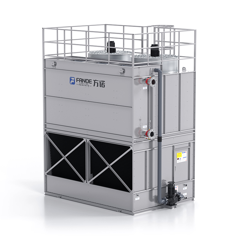
Counterflow Closed-Circuit Cooling Tower
In a counterflow arrangement, air enters from the bottom of the tower and moves upward through the coil bundle, while the spray water falls downward over the coil surfaces from distribution nozzles at the top. The hot process fluid entering the coil is exposed to the warmest spray water, while the cooled process fluid exiting the coil encounters the freshest incoming air at the bottom. This counter-directional flow maximizes the temperature driving force throughout the coil, resulting in a smaller required coil surface area for a given heat duty compared to crossflow designs. Counterflow closed-circuit towers are generally more compact and thermally efficient per unit of footprint, but they require more fan energy to draw air upward against gravity and through the wet coil bundle.
Crossflow Closed-Circuit Cooling Tower
In a crossflow configuration, air moves horizontally through the coil bundle while spray water falls vertically downward. The separation of air and water flow paths simplifies the tower structure and typically results in lower static pressure drop across the air path, which means lower fan energy consumption compared to counterflow designs handling the same heat load. Crossflow closed-circuit towers tend to have a longer footprint but shorter height, which can be advantageous in rooftop or mechanical penthouse installations with headroom constraints. The thermal efficiency per unit of coil surface is slightly lower than counterflow, but this is typically compensated by the reduced operating cost from lower fan motor energy demand.
Closed-Circuit Tower with External Heat Exchanger
A third configuration uses a standard open cooling tower paired with a dedicated plate or shell-and-tube heat exchanger installed between the open tower and the process circuit. The open tower handles the evaporative heat rejection, and the heat exchanger provides the thermal barrier that keeps the process fluid isolated. This approach delivers the contamination protection of a closed-circuit system while using the lower approach temperature capability of an open tower — essentially the best of both designs in thermal terms. The trade-off is additional capital cost (the heat exchanger plus the connecting piping and an additional pump circuit), increased footprint, and an extra heat transfer step that still adds to the overall approach temperature. This configuration is widely used in large HVAC chiller plants where both low condenser water temperatures and process fluid cleanliness are required simultaneously.
Key Applications Where Closed Type Cooling Towers Are the Right Choice
While closed-circuit cooling towers are appropriate across a broad range of industrial and commercial applications, there are specific situations where the closed design is not just preferable but practically essential. These are the use cases where the contamination protection and system integrity benefits of the closed loop justify the higher capital cost and approach temperature penalty.
- Industrial process cooling with sensitive equipment — Hydraulic systems, compressor aftercoolers, furnace cooling circuits, injection molding temperature control units, and laser cooling systems all involve equipment where contaminated cooling water causes catastrophic damage. A single season of open cooling tower water flowing through a precision hydraulic cooler can deposit enough scale and biological fouling to block the passages entirely. Closed type cooling towers prevent this by ensuring clean, controlled fluid circulates through the process equipment at all times.
- Data center and server room cooling — The cooling infrastructure for high-density computing cannot tolerate contamination-driven failures. Process cooling water (PCW) loops in data centers typically use closed-circuit cooling towers or dry coolers with glycol as the primary heat rejection path. Any interruption in cooling directly causes server downtime, making the reliability and contamination protection of the closed loop a core design requirement rather than an optional upgrade.
- Medical and pharmaceutical manufacturing — GMP manufacturing environments, hospital HVAC systems, and pharmaceutical process cooling require documented water quality control. Open cooling tower water systems introduce biological contamination risks — including Legionella — into the building infrastructure. Closed primary circuits with carefully managed secondary spray water loops can meet the regulatory and contamination control standards that open systems cannot.
- Cold-climate installations requiring freeze protection — When cooling towers must operate in sub-zero ambient temperatures, adding glycol to an open cooling tower system requires treating the entire water volume — potentially tens of thousands of liters — with antifreeze chemistry and managing the resulting impact on heat transfer efficiency. In a closed type cooling tower, glycol is added only to the primary circuit (typically a much smaller volume), while the secondary spray water circuit can be drained seasonally. This is dramatically simpler and more cost-effective for facilities in northern climates.
- HVAC systems where downstream coil protection is a priority — Condenser water circuits serving water-cooled chillers benefit significantly from the reduced fouling protection offered by the closed primary loop. Chiller condenser tube fouling directly increases condensing pressure and reduces chiller efficiency — a 0.0005-inch fouling layer on condenser tubes can increase chiller energy consumption by 10–15%. Keeping condenser water clean by using a closed-circuit cooling tower maintains chiller performance over the equipment's full life cycle.
Sizing a Closed Type Cooling Tower: The Parameters That Drive Selection
Correctly sizing a closed-circuit cooling tower requires specifying several interdependent parameters. Errors in any one of them result in a unit that is either oversized (wasting capital) or undersized (failing to meet the required process outlet temperature at peak load). Here is what you need to define before engaging a manufacturer or consulting engineer for a selection.
Heat Load (kW or TR)
The total heat rejection requirement of the closed-circuit cooler, expressed in kilowatts or tons of refrigeration. For process cooling, this is the sum of all heat inputs from the equipment being cooled. For HVAC condenser water applications, it is the chiller's heat rejection capacity at design conditions — typically 20–30% higher than the chiller's cooling capacity, depending on the COP. Specifying heat load at the actual peak operating condition (not a nominal or average figure) is essential; a closed type cooling tower that is adequate at average load but insufficient at summer peak load will cause process upsets or chiller faults at exactly the time when reliability matters most.
Process Fluid Inlet and Outlet Temperatures
The temperature of the process fluid entering the tower (the hot side inlet) and the required temperature leaving the tower (the cooled outlet) define the temperature range across which the tower must work. Common design conditions for HVAC condenser water are 95°F (35°C) inlet, 85°F (29.4°C) outlet — a 10°F (5.6°C) range. Industrial process applications often have wider ranges. A wider range (for the same heat load) allows a smaller flow rate and potentially a more compact tower; a narrower range requires higher flow rates and a larger coil surface area.
Design Wet-Bulb Temperature
The ambient wet-bulb temperature is the atmospheric condition against which the closed type cooling tower performs. This is the temperature an evaporatively cooled surface approaches under the prevailing humidity conditions. Cooling tower selection is always done against the local design wet-bulb temperature — typically the 1% or 0.4% exceedance value from ASHRAE climate data for the installation location. The difference between the required process outlet temperature and the design wet-bulb temperature is the approach temperature. For a closed-circuit tower, approach temperatures of 8–15°F (4.4–8.3°C) are typical at design conditions. Specifying an approach temperature that is too optimistic will result in a unit that cannot meet the required outlet temperature during the hottest days of the year.
Flow Rate
The volumetric flow rate of the primary process fluid through the closed-circuit coil, typically expressed in gallons per minute (GPM) or liters per second (L/s). Flow rate is derived from the heat load and the required temperature range: Flow (GPM) = Heat Load (BTU/hr) ÷ (500 × ΔT °F). Getting the flow rate right matters not just for thermal performance but for pressure drop across the coil — which determines the pump size needed in the primary circuit.
Water Treatment for Closed Type Cooling Towers
A common misconception about closed-circuit cooling towers is that the closed primary loop eliminates the need for water treatment. While the primary circuit does require significantly less treatment than an equivalent open system, the secondary spray water circuit — the loop that circulates water over the coil bundle — operates under essentially the same conditions as an open cooling tower and requires a comprehensive water treatment program. Neglecting the secondary circuit leads to scale buildup on the coil exterior, microbiological fouling, and Legionella risk, all of which degrade tower performance and create potential public health liability.
Secondary Circuit Water Treatment Requirements
The secondary spray water in a closed type cooling tower is exposed to the atmosphere, concentrates dissolved minerals through evaporation, and operates at temperatures that support biological growth. The core treatment requirements are:
- Scale and corrosion inhibitors — Evaporation concentrates dissolved calcium, magnesium, and silica in the sump water. Without scale inhibitors (typically threshold agents or polymeric dispersants), carbonate scale deposits form on the coil exterior surface, acting as an insulating layer that directly reduces heat transfer efficiency. A 1 mm scale layer on the coil exterior can reduce the tower's thermal output by 10–20%. Corrosion inhibitors protect the sump basin, distribution system, and coil exterior from oxidative attack.
- Biocide treatment — Spray water temperatures in the range of 20–45°C (68–113°F) are ideal for Legionella and other bacterial growth. An oxidizing biocide program — typically based on chlorine (sodium hypochlorite) or bromine compounds — maintained at appropriate residual levels provides continuous biological control. Non-oxidizing biocides are added periodically as shock treatments to address organisms that develop resistance to the primary oxidizing program. Free chlorine residual in the sump should be maintained between 0.5–2.0 ppm.
- Blowdown control — As water evaporates, dissolved solids concentrate in the sump. The concentration ratio (cycles of concentration) must be controlled through blowdown — the controlled discharge of concentrated sump water and replacement with fresh makeup water. Most closed type cooling tower secondary circuits are designed to operate at 3–5 cycles of concentration, controlled either by a timed blowdown valve or a conductivity controller that automates blowdown based on measured dissolved solids.
Primary Circuit Treatment
The closed primary circuit does not evaporate or exchange water with the atmosphere, so it does not concentrate or accumulate the same contamination load as the secondary circuit. However, it still requires initial treatment and periodic monitoring. Initial fill water should be treated with a corrosion inhibitor appropriate to the metals in the circuit (typically molybdate or nitrite-based inhibitors for mixed-metal systems). If glycol is used for freeze protection, glycol concentration should be maintained at the level appropriate for the lowest expected ambient temperature, and checked at least annually — glycol degrades over time, and degraded glycol becomes corrosive. pH should be maintained between 7.5 and 9.5, and conductivity monitored to detect any cross-contamination from the secondary circuit, which would indicate a coil leak.
Maintenance Schedule and Inspection Points
Closed type cooling towers are more forgiving than open towers in terms of contamination-driven maintenance, but they are not maintenance-free. A structured preventive maintenance program keeps the tower performing at rated capacity, extends equipment life, and satisfies the regulatory requirements that apply to evaporative cooling equipment in most jurisdictions.
- Weekly — Check and log secondary circuit water chemistry: free chlorine or bromine residual, pH, and conductivity. Inspect sump water for visible turbidity, debris, or biological growth. Verify spray nozzle coverage by checking that all zones of the coil surface are being wetted. Check fan motor amperage against baseline — deviations indicate mechanical problems before failure occurs.
- Monthly — Inspect drift eliminators for physical damage, blockage, or displacement. Damaged drift eliminators release contaminated aerosols into the surrounding air, bypassing the biological control program regardless of water chemistry. Clean debris from sump and basin. Lubricate fan shaft bearings and check belt tension (if belt-drive fans are used). Inspect coil exterior for visible scale deposits — white or gray deposits indicate that the scale inhibitor dosing is insufficient or the blowdown rate is too low.
- Quarterly — Test secondary circuit water for Legionella and total bacteria count (Heterotrophic Plate Count). HPC should remain below 10,000 cfu/mL; any Legionella detection above the regulatory action level requires immediate remediation. Flush low-flow zones and dead-leg sections of the secondary circuit — stagnant water is the primary amplification site for Legionella regardless of bulk water treatment. Inspect coil tubes for corrosion pitting or leaks by checking for elevated conductivity or glycol presence in the secondary circuit.
- Annual — Complete mechanical inspection of fan assembly: blade condition, hub integrity, motor condition, vibration baseline measurement. Clean coil bundle exterior using low-pressure water wash or chemical cleaning if scale has accumulated beyond what the inhibitor program can control. Drain and inspect the sump basin for corrosion, cracks, and sediment accumulation. Test glycol concentration and inhibitor levels in the primary circuit. Verify that makeup water float valve and blowdown control valve operate correctly. Conduct a full thermal performance test and compare against the original design specification to quantify any efficiency loss.
Seasonal shutdown and restart procedures deserve particular attention. The period immediately after a seasonal shutdown — when the tower has been sitting inactive with stagnant water — is the highest-risk point in the Legionella growth cycle. Before restarting after any extended downtime, the secondary circuit should be drained, cleaned, refilled with fresh water, and subjected to a hyperchlorination shock treatment (10–20 ppm free chlorine for at least 60 minutes) before the system is returned to service. This procedure, along with documented water quality records, forms the core of a compliant Water Management Program under ASHRAE 188 and equivalent regulatory frameworks in most jurisdictions.
Common Problems and How to Diagnose Them
Even well-maintained closed type cooling towers encounter operational issues. Recognizing the symptoms of common problems early prevents them from escalating into system outages or regulatory incidents.
- Insufficient cooling — process outlet temperature above target — The most common cause is scale buildup on the coil exterior, reducing thermal conductivity. Secondary causes include insufficient spray water coverage (blocked or misaligned nozzles), reduced fan airflow (worn belts, fouled air intakes, damaged fan blades), or ambient conditions exceeding the design wet-bulb temperature. Start diagnostics by verifying ambient wet-bulb temperature against the design condition, then inspect coil surface visually, then check spray coverage and fan performance.
- Elevated sump conductivity despite correct blowdown — Indicates either a coil leak (process fluid leaking into the secondary circuit) or a makeup water quality problem. Test the sump water for glycol (if the primary circuit uses glycol) or measure the sump conductivity against the makeup water conductivity — a conductivity spike beyond what the cycles of concentration formula predicts points to an external source of dissolved solids, most likely a coil perforation.
- White deposits on coil exterior — Carbonate or silica scale from the secondary circuit. Indicates the scale inhibitor dosing rate is insufficient, the cycles of concentration are too high (blowdown rate too low), or the inhibitor type is mismatched to the makeup water chemistry. Have the makeup water analyzed for hardness, alkalinity, and silica, and adjust the treatment program accordingly.
- Biological slime in sump or on fill media — Indicates that biocide residual is not being maintained. Check biocide dosing pump operation, verify that the correct biocide product is being used and at the correct dosing rate, and check for chemical incompatibility between the biocide and the scale inhibitor (some combinations neutralize each other). Shock-dose with a non-oxidizing biocide and review the water chemistry program with a treatment specialist.
- Unusual vibration or noise from fan assembly — Fan blade imbalance (from ice accumulation, scale deposits on blades, or physical damage), worn bearings, or loose mechanical connections. Do not continue operating a vibrating cooling tower fan without investigation — imbalance-driven fatigue failures in fan assemblies can be catastrophic. Shut down the affected fan and conduct a physical inspection before restart.


 Eng
Eng English
 中文简体
中文简体
 What Is an Open Circuit Cooling Tower and How Does It Work?
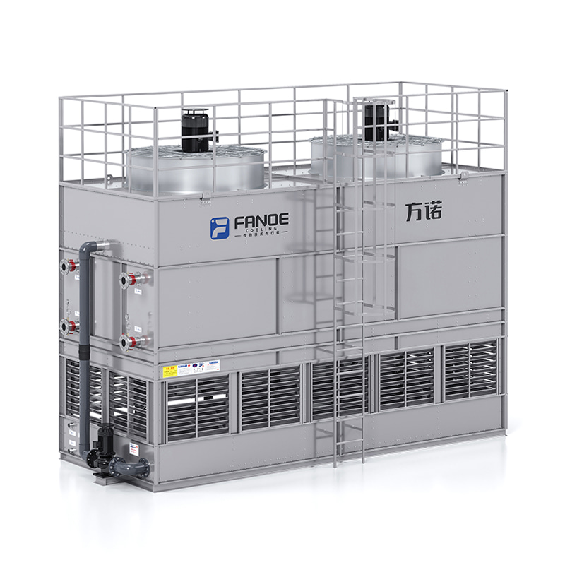 What Is a Closed Type Cooling Tower and When Should You Use One?How a Closed Type Cooling Tower Actually Works A closed type cooling tower — also widely referred to as a closed-circuit cooling tower, closed-loop c...
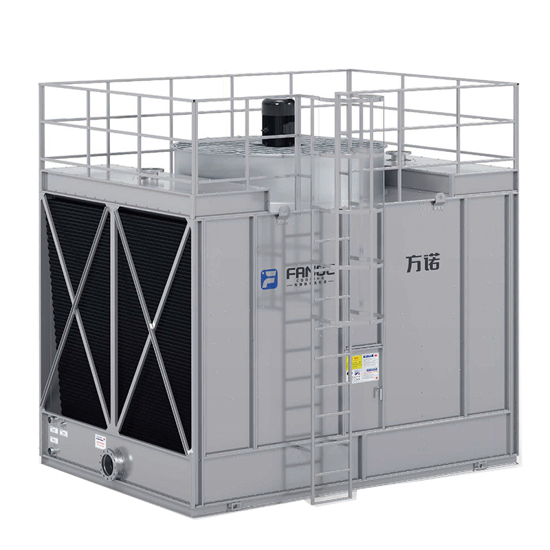 Cooling Tower Guide: Types, How They Work & Selection CriteriaHow a Cooling Tower Actually Works A cooling tower is a heat rejection device that removes waste heat from a process or building system by transferrin...
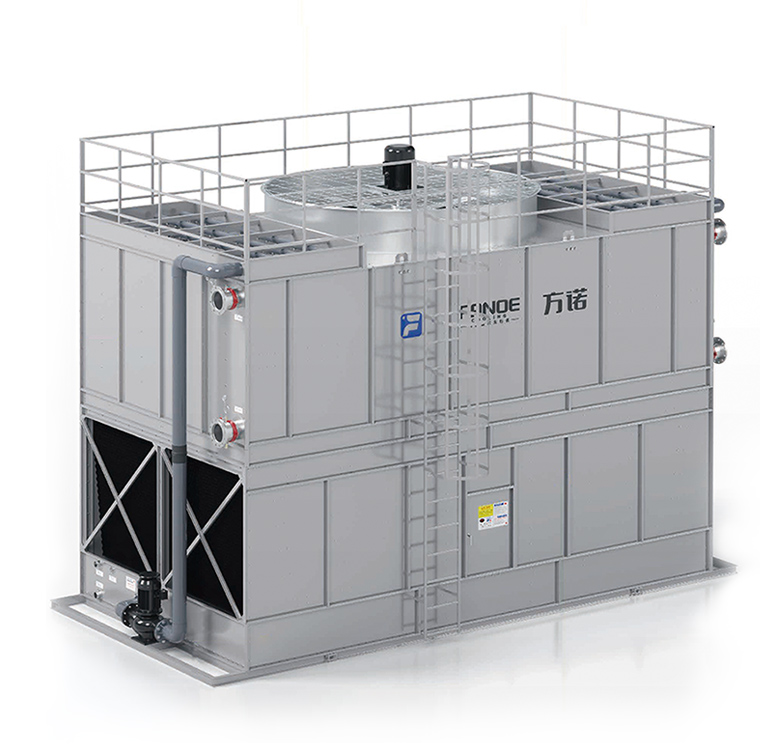 Industrial Cooling Towers: How They Work, Types, and How to Keep Them Running RightWhat Industrial Cooling Towers Do and Why They Matter Industrial cooling towers are large heat rejection systems designed to remove excess thermal en...
 Evaporative Condenser Explained: How It Works, How to Choose One, and How to Keep It RunningWhat Is an Evaporative Condenser and How Does It Work? An evaporative condenser is a heat rejection device that combines the functions of a condenser ...