How a Cooling Tower Actually Works
A cooling tower is a heat rejection device that removes waste heat from a process or building system by transferring it to the atmosphere through the evaporation of water. The fundamental operating principle is straightforward: warm water from the process being cooled — a chiller condenser, an industrial heat exchanger, or a power generation system — is distributed across the cooling tower's fill media, where it flows in thin films or droplets through a moving air stream. A small portion of that water evaporates, and the energy required to convert liquid water to vapor is extracted from the remaining water, cooling it. The cooled water collects in the tower basin and is pumped back to the process to absorb more heat, completing the cycle.
The efficiency of this process depends on the wet-bulb temperature of the ambient air — the temperature a surface reaches when water evaporates from it under the prevailing humidity conditions — rather than the dry-bulb (standard thermometer) temperature. This is why cooling towers can cool water to temperatures approaching, but not reaching, the wet-bulb temperature of the surrounding air. In hot, humid climates, the wet-bulb temperature is higher and cooling tower performance is more limited; in hot, dry climates, the larger gap between wet-bulb and dry-bulb temperatures allows more effective evaporative cooling.
The water that evaporates carries heat away from the system, but it also means the tower continuously loses water from the circulating volume. This evaporative loss — typically 1 to 3 percent of the circulating water flow rate per hour of operation — must be replaced with makeup water. As water evaporates and pure water leaves the system as vapor, dissolved minerals concentrate in the remaining water. Managing this concentration — through blowdown, where a portion of concentrated circulating water is discharged and replaced with fresh makeup water — is one of the core operational requirements of any cooling tower system.
Open Circuit vs. Closed Circuit Cooling Towers
The most fundamental design distinction in cooling tower selection is between open circuit (also called open loop) and closed circuit configurations. These two designs handle the relationship between the process fluid and the evaporating water differently, and the choice between them has significant implications for system performance, water quality management, and maintenance requirements.
Open Circuit Cooling Towers
In an open circuit cooling tower, the process water itself is the water that flows over the fill media and is directly exposed to the air stream. Hot process water enters the tower at the top, is distributed over the fill, and the partially cooled water collects in the basin below before being pumped back to the process. Because the circulating water is exposed directly to air, it picks up airborne dust, biological contaminants, and atmospheric gases, and continuously concentrates dissolved solids through evaporation. Open circuit cooling towers are the most thermally efficient configuration because the process water directly participates in evaporative cooling with no intermediate heat transfer step. They are the most widely used type in HVAC chiller systems, industrial process cooling, and power generation applications where the circulating water quality can be managed through chemical treatment and filtration programs.
Closed Circuit Cooling Towers
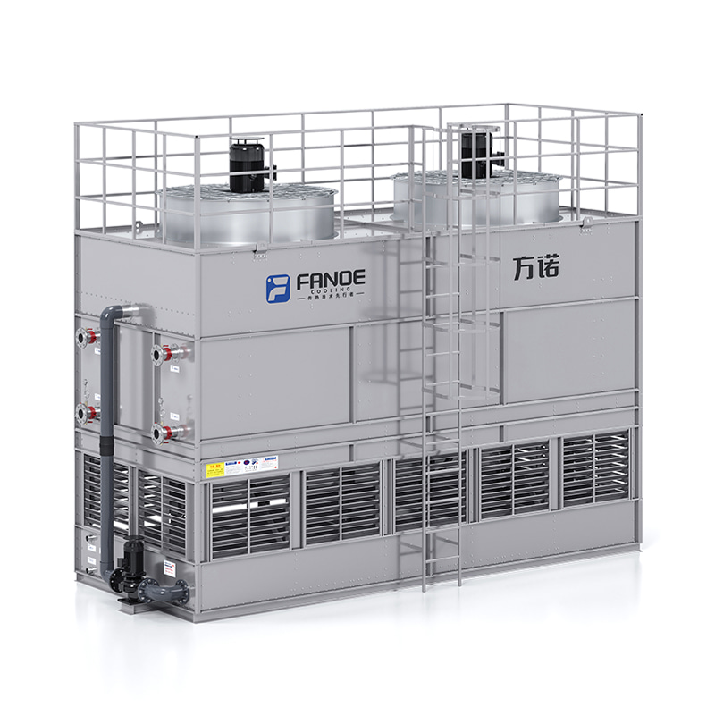
A closed circuit cooling tower — also called a fluid cooler or evaporative cooler — keeps the process fluid in a sealed coil or heat exchanger inside the tower. The process fluid flows through the coil while a separate spray water system wets the outside of the coil surface; it is this spray water that evaporates and provides cooling. The process fluid never contacts the air stream or the spray water directly. This separation keeps the process fluid clean and free of airborne contamination, which is critical for applications where fluid purity matters — glycol systems, precision manufacturing processes, data center cooling, and any application where the process equipment has tight water quality tolerances. The trade-off is slightly lower thermal efficiency compared to an open circuit tower, because the process fluid must transfer heat through the coil wall to the spray water before evaporative cooling occurs.
Cooling Tower Types by Draft Mechanism
Beyond the open/closed circuit distinction, cooling towers are further classified by how air moves through the tower — the draft mechanism. This classification determines fan placement, energy consumption characteristics, plume behavior, and installation footprint, and it is one of the primary selection criteria for any cooling tower specification.
Natural Draft Cooling Towers
Natural draft cooling towers use the density difference between the warm, humid air inside the tower and the cooler ambient air outside to create airflow — no fans are required. The iconic hyperboloid concrete structures seen at large power stations are natural draft cooling towers. Their extreme height — often 100 to 200 meters — is what creates the chimney effect that drives sufficient airflow through the fill at the base of the structure. Natural draft towers have essentially zero fan energy consumption and very low maintenance requirements related to the air-moving system, but they require substantial capital investment in civil structures, occupy large footprints, and are only thermally viable at very large scales — typically above 100 MW of heat rejection capacity. They are not practical for HVAC or small-to-medium industrial applications.
Mechanical Draft — Forced Draft
Forced draft cooling towers position the fan at the air inlet — at the base or side of the tower — and push air upward through the fill media. The fan operates against relatively low static pressure since it is handling ambient air at inlet conditions. Forced draft towers are compact, and because the fan motor and drive components are at the base of the unit rather than at the top, they are more accessible for maintenance than induced draft alternatives. However, the warm, saturated exhaust air discharged at the top of a forced draft tower has a tendency to recirculate back to the air inlet, particularly in calm wind conditions, which reduces thermal performance. Forced draft designs are common in smaller packaged cooling tower units and in applications where top access for fan maintenance is constrained.
Mechanical Draft — Induced Draft
Induced draft cooling towers mount the fan at the top of the tower and draw air upward through the fill by suction. This is the most widely used configuration in industrial and commercial HVAC cooling towers. The fan discharges warm, saturated exhaust air upward at high velocity, which carries the plume away from the tower and substantially reduces the risk of recirculation compared to forced draft designs. Induced draft towers achieve more predictable and consistent airflow distribution across the fill media, and the high-velocity discharge minimizes ground-level plume effects. The trade-off is that the fan and drive components are at the top of the tower, making maintenance access more challenging, and the fan operates in hot, humid air rather than cool inlet air, which slightly reduces fan efficiency.
Fan-Assisted Natural Draft
Fan-assisted natural draft towers combine a modest mechanical draft system with the natural buoyancy effect of a tall tower shell to achieve a hybrid performance profile — lower fan energy consumption than fully mechanical draft towers while avoiding the extreme civil construction costs of purely natural draft designs. These are specialized configurations used primarily in large industrial applications and are not commonly encountered in standard commercial or light industrial cooling tower markets.
Crossflow vs. Counterflow: How Air and Water Meet in the Tower
Within the mechanical draft category, cooling towers are further divided by the geometric relationship between the water flow path and the airflow path through the fill media. This distinction — crossflow versus counterflow — affects thermal efficiency, fill media selection, maintenance access, and tower height-to-footprint ratio.
Counterflow Cooling Towers
In a counterflow tower, water flows vertically downward through the fill while air flows vertically upward — in the opposite direction to the water. This opposing flow arrangement creates the most thermally efficient contact between water and air of any fill geometry because the coldest water at the bottom of the fill contacts the driest incoming air, and the hottest water at the top contacts the most saturated exhaust air — maximizing the driving force for heat and mass transfer throughout the fill depth. Counterflow towers tend to have a smaller footprint for a given heat rejection capacity than crossflow designs, but they require a higher pumping head to lift the hot water to the top distribution system, and access to the fill media for inspection and cleaning is more restricted.
Crossflow Cooling Towers
In a crossflow tower, water flows vertically downward through the fill while air flows horizontally across the fill from the sides of the tower. Hot water is distributed through gravity-fed distribution basins at the top of the fill, which require no pumping pressure and are easily accessible for cleaning and inspection. The fill panels in a crossflow tower are typically accessible from the air inlet face, making replacement and maintenance simpler than in counterflow designs. The thermal efficiency of crossflow towers is slightly lower than counterflow for equivalent fill volume because the airflow is not perfectly opposed to the water flow, but for many applications this difference is modest and the maintenance and pumping advantages of crossflow designs make them the preferred choice.
| Feature |
Counterflow |
Crossflow |
| Thermal Efficiency |
Higher |
Slightly lower |
| Footprint |
Smaller |
Larger |
| Pumping Head Required |
Higher |
Lower |
| Fill Access for Maintenance |
More restricted |
Easier |
| Distribution System |
Pressurized spray nozzles |
Gravity-fed open basins |
| Tower Height |
Taller for equivalent capacity |
Lower profile |

Fill Media: The Component That Does Most of the Work
Fill media — also called packing — is the structured or random material inside the cooling tower that breaks the water into thin films or small droplets to maximize the surface area available for heat and mass transfer with the air stream. Fill accounts for the majority of the actual cooling performance of a tower, and fill selection has a significant impact on thermal efficiency, pressure drop, fouling resistance, and maintenance requirements.
Film Fill
Film fill consists of thin, corrugated or textured PVC sheets arranged in close-packed blocks through which water flows as a thin film on the sheet surfaces. The large surface area created by the thin water films in close proximity to the air stream makes film fill the most thermally efficient fill type — more heat transfer per unit volume than any alternative. Film fill is the standard choice for clean water applications in HVAC chiller cooling, power generation, and light industrial cooling where water quality can be maintained through chemical treatment. Its limitation is susceptibility to fouling: if the circulating water carries suspended solids, biological growth, or scale-forming minerals, the narrow passages between film fill sheets can clog, reducing airflow and water distribution and eventually requiring fill replacement.
Splash Fill
Splash fill uses horizontal bars, slats, or grid structures to break falling water into droplets as it cascades downward through the fill zone. The larger open spaces between splash fill elements make it far more resistant to fouling than film fill — suspended solids, biological growth, and even moderate scaling pass through without blocking the fill. Splash fill is the appropriate choice for cooling towers handling water with high suspended solids, significant biological load, or poor water quality that cannot be adequately controlled by chemical treatment alone. Thermal efficiency is lower than film fill for equivalent fill volume, so splash fill towers are physically larger for a given heat rejection duty, but their reliability in difficult water quality conditions often outweighs the size penalty.
Hybrid Fill
Hybrid fill arrangements combine a lower section of splash fill with an upper section of film fill in the same tower. The splash fill zone at the bottom handles the initial water quality challenges — breaking up any solids that enter with the water — while the film fill zone above it provides the thermal efficiency needed to achieve the required approach temperature. Hybrid fill is increasingly used as a practical compromise in applications where water quality is variable or moderately challenging, providing better fouling resistance than all-film fill without the full thermal performance penalty of all-splash fill.
Cooling Tower Water Treatment: What Happens If You Skip It
Water treatment is not optional for any operating cooling tower — it is a core operational requirement that determines the long-term performance, reliability, and safety of the system. The combination of continuous water evaporation, warm temperatures, sunlight exposure, and airborne contamination creates conditions that actively promote scale formation, corrosion, and biological growth in the absence of a managed treatment program.
Scale and Mineral Deposits
As water evaporates from the cooling tower, dissolved minerals — primarily calcium carbonate, calcium sulfate, and silica — concentrate in the remaining circulating water. When concentration reaches saturation, these minerals precipitate out of solution and deposit as scale on heat transfer surfaces, fill media, basin walls, and distribution nozzles. Even thin scale deposits (1–2mm) on heat exchanger surfaces significantly reduce heat transfer efficiency, increasing process temperatures and energy consumption. Scale control requires managing the cycles of concentration through blowdown — periodically discharging a portion of the concentrated circulating water and replacing it with fresh makeup water — combined with scale inhibitor chemical treatment that keeps minerals in solution at elevated concentrations.
Corrosion
The combination of dissolved oxygen, elevated temperature, low pH from CO₂ absorption, and chloride ions from makeup water creates a corrosive environment for metal components in a cooling tower system — particularly steel basins, pipework, and heat exchanger tubes. Corrosion inhibitors — typically molybdate, phosphonate, or azole-based compounds depending on the metals in the system — are added to the circulating water to form a protective film on metal surfaces. Maintaining correct inhibitor residuals through regular monitoring and dosing is essential to protect capital equipment and prevent premature failure of system components.
Biological Growth and Legionella Risk
Warm, nutrient-rich cooling tower water is an ideal growth environment for bacteria, algae, and biofilm-forming microorganisms. Of particular concern is Legionella pneumophila — the bacterium responsible for Legionnaires' disease — which thrives in water temperatures between 20°C and 45°C and can be dispersed in the aerosol drift from an operating cooling tower to cause serious respiratory illness in people nearby. Legionella control is a legal requirement in many jurisdictions and demands a formal water management program including biocide treatment (typically with alternating oxidizing and non-oxidizing biocides), regular monitoring of bacterial counts, physical cleaning and disinfection of the tower at defined intervals, and documented risk assessments. Neglecting cooling tower biological treatment is not only an operational problem — it is a public health and legal liability issue.
Key Selection Criteria When Specifying a Cooling Tower
Cooling tower selection for a specific application requires defining the thermal duty and ambient conditions with enough precision to allow the tower manufacturer to size the equipment correctly. Undersized towers cannot achieve the required cold water temperature, which causes process temperatures to rise and reduces chiller or process equipment efficiency. Oversized towers waste capital cost and occupy more space than necessary. The following parameters define the thermal specification for any cooling tower selection.
- Heat rejection duty (kW or tons of refrigeration): The total rate of heat that the tower must remove from the circulating water. For chiller applications, this includes both the chiller's cooling capacity and the compressor heat input — typically 1.25 to 1.35 times the chiller cooling capacity in kW.
- Hot water temperature (HWT): The temperature of the warm water entering the cooling tower from the process or condenser. This is the temperature that must be reduced by the tower.
- Cold water temperature (CWT): The target temperature of the cooled water leaving the tower basin and returning to the process. The difference between HWT and CWT is the range — typically 5°C to 10°C for HVAC applications.
- Design wet-bulb temperature: The wet-bulb temperature of the ambient air at design conditions — typically the peak summer wet-bulb temperature at the installation site. The difference between CWT and the design wet-bulb temperature is the approach, which determines how difficult the cooling duty is. Small approaches (3–5°C) require larger, more expensive towers than larger approaches (8–10°C).
- Water flow rate (m³/hr or GPM): The volumetric flow of circulating water through the tower, determined by the heat duty and the temperature range.
- Site constraints: Available footprint, height restrictions, proximity to air intakes or occupied areas (for noise and drift considerations), structural loading limits, and prevailing wind direction all influence tower type selection and placement.
- Water quality: Makeup water hardness, silica content, chloride levels, and the intended cycles of concentration determine fill type selection, materials of construction, and the water treatment program required.
Routine Maintenance Tasks That Keep a Cooling Tower Running Efficiently
A cooling tower that is not regularly maintained deteriorates in both thermal performance and mechanical reliability, and the consequences compound over time — scale reduces heat transfer, fouled fill increases fan power consumption, corroded components fail, and biological growth creates health risks. A structured maintenance program prevents all of these outcomes and extends equipment service life significantly.
- Basin cleaning: Sediment, biological growth, and debris accumulate in the cold water basin and become a nutrient source for bacteria. Basin cleaning — removing accumulated sediment, scrubbing surfaces, and inspecting basin integrity — should be performed at least annually and more frequently in high-fouling environments.
- Fill inspection and cleaning: Film fill should be inspected annually for scale deposits, biological fouling, and physical damage. Heavily fouled fill sections significantly reduce thermal performance and airflow, and may need to be cleaned with high-pressure water or, in severe cases, replaced.
- Distribution system inspection: Spray nozzles and distribution basins should be checked for blockage, damage, and proper flow distribution. Uneven water distribution across the fill reduces thermal performance and accelerates localized fouling in under-wetted areas.
- Fan and drive maintenance: Fan blades should be inspected for damage and pitch consistency; drive belts (if applicable) checked for wear and tension; gearboxes lubricated per manufacturer schedules; and motor current draw monitored to detect bearing wear or aerodynamic loading changes that indicate fill fouling.
- Drift eliminators: These components, which capture water droplets from the exhaust air to minimize water loss and aerosol discharge, should be inspected for physical integrity and proper seating. Damaged or missing drift eliminators increase water consumption, contribute to visible plume formation, and — critically — increase the dispersal of any biological contaminants in the circulating water to the surrounding environment.
- Water quality monitoring: Conductivity (as a proxy for dissolved solids concentration), pH, biocide residuals, inhibitor levels, and microbiological counts should all be monitored at frequencies defined by the water management plan — typically weekly for chemical parameters and monthly or quarterly for microbiological testing, with more frequent testing during high-risk periods.


 Eng
Eng English
 中文简体
中文简体
 What Is a Closed Type Cooling Tower and When Should You Use One?How a Closed Type Cooling Tower Actually Works A closed type cooling tower — also widely referred to as a closed-circuit cooling tower, closed-loop c...
 Cooling Tower Guide: Types, How They Work & Selection CriteriaHow a Cooling Tower Actually Works A cooling tower is a heat rejection device that removes waste heat from a process or building system by transferrin...
 Industrial Cooling Towers: How They Work, Types, and How to Keep Them Running RightWhat Industrial Cooling Towers Do and Why They Matter Industrial cooling towers are large heat rejection systems designed to remove excess thermal en...
 Evaporative Condenser Explained: How It Works, How to Choose One, and How to Keep It RunningWhat Is an Evaporative Condenser and How Does It Work? An evaporative condenser is a heat rejection device that combines the functions of a condenser ...