What a Cross-flow Evaporative Condenser Actually Does
A cross-flow evaporative condenser is a heat rejection device used in refrigeration and HVAC systems that removes heat from a hot refrigerant vapor by combining two simultaneous cooling mechanisms: sensible cooling from water evaporation and latent heat rejection through direct air contact. The result is a condenser that rejects heat far more efficiently than a conventional air-cooled condenser — often operating at condensing temperatures 10°C to 15°C lower for the same ambient conditions — while using significantly less water than a traditional cooling tower paired with a shell-and-tube condenser.
In the cross-flow configuration specifically, the airflow moves horizontally across the coil bundle — perpendicular to both the falling water film and the refrigerant flow path inside the tubes. This horizontal air movement is the defining characteristic that distinguishes cross-flow evaporative condensers from their counterflow counterparts, where air travels vertically upward through the fill or coil section. The cross-flow arrangement produces a compact, low-profile unit that is particularly well-suited to installations with height restrictions, such as rooftop mechanical rooms or basement plant rooms with limited vertical clearance.
The refrigerant — typically ammonia (R717), CO₂, or a halocarbon such as R404A, R448A, or R507 — enters the condenser coil as a hot superheated vapor from the compressor discharge. As it passes through the coil, the combination of the water film flowing over the exterior of the tubes and the evaporation driven by the moving air stream strips heat from the refrigerant, condensing it to a subcooled liquid before it exits to the expansion device. The entire heat rejection process occurs within the condenser itself, eliminating the need for a separate cooling tower and the associated water treatment infrastructure of an intermediate glycol circuit.
Cross-flow vs. Counterflow Evaporative Condensers: Key Differences
The choice between cross-flow and counterflow evaporative condenser configurations is one of the first engineering decisions in system design, and it has significant implications for footprint, efficiency, noise, and maintenance access. Understanding the practical differences between the two layouts helps engineers and facility managers make the right selection for their specific application.
Airflow Path and Unit Geometry
In a counterflow evaporative condenser, fans draw air vertically upward through the coil section, moving in the opposite direction to the falling water film. This counterflow arrangement creates a very favorable temperature gradient between the air and the water/refrigerant, theoretically maximizing heat transfer efficiency per unit of coil area. However, the vertical air path requires significant unit height — counterflow units are tall, which can be a serious problem in constrained installation environments.
Cross-flow evaporative condensers move air horizontally through the coil section. This produces a lower, wider unit profile that fits under ceilings, into shipping containers, or on low-clearance rooftops where a counterflow unit simply cannot be accommodated. The horizontal air path means that the temperature driving force between air and coil is not as uniformly optimal as in counterflow, but modern cross-flow coil designs and optimized water distribution systems narrow this efficiency gap significantly — the practical difference in heat rejection performance between well-designed cross-flow and counterflow units is often 3–8% in favor of counterflow, which is acceptable given the footprint advantages the cross-flow geometry provides.
Fan Arrangement and Noise Characteristics
Cross-flow evaporative condensers typically use axial fans mounted on the sides of the unit to draw or force air horizontally through the coil section. Fan noise in cross-flow units is often directed laterally, which can be an advantage or disadvantage depending on where neighboring buildings or noise-sensitive areas are located relative to the unit. Counterflow units exhaust air vertically upward from the top of the unit, which tends to project noise upward and dissipate it more quickly over surrounding areas. Where noise is a key constraint — such as in urban rooftop installations near residences — the fan location and discharge direction relative to the site layout should be carefully evaluated for both configurations.
Drift and Plume Management
Water drift — fine droplets carried out of the unit by the airstream — is an important consideration for both configurations, but the horizontal airflow in cross-flow units creates different drift management challenges. In cross-flow designs, drift eliminators are positioned at the air outlet face of the unit to intercept entrained water droplets before they leave the unit. Well-designed cross-flow evaporative condensers achieve drift rates below 0.001% of the circulated water flow rate with modern eliminator profiles, which is compliant with Legionella risk management guidelines in most regulatory jurisdictions.
Core Components of a Cross-flow Evaporative Condenser
A cross-flow evaporative condenser is an assembly of several interconnected systems, each of which must perform reliably for the unit to deliver its rated heat rejection capacity. Knowing what each component does — and what can go wrong with it — is essential for both procurement and maintenance planning.
Refrigerant Coil
The refrigerant coil is the thermal heart of the cross-flow evaporative condenser. It consists of a bundle of bare or finned tubes through which the refrigerant flows, arranged in a serpentine or header-and-circuit configuration to maximize residence time within the coil. For ammonia systems, coils are almost universally constructed from hot-dip galvanized carbon steel or stainless steel to resist the aggressive corrosion that ammonia initiates with copper. For halocarbon systems, copper tubes with steel headers are common, though all-stainless steel or galvanized steel coils are also available and preferred in corrosive atmospheric environments near coastlines or industrial sites.
The coil design determines the condensing temperature that can be achieved at a given heat rejection load and wet-bulb temperature. Coil circuits are arranged so that the refrigerant vapor enters at the top of the coil (where the water film is warmest) and the subcooled liquid exits at the bottom — a design choice that optimizes the temperature driving force between the refrigerant and the water film throughout the coil depth.
Water Distribution System
Uniform water distribution over the entire coil surface is critical to achieving the rated heat rejection performance. In cross-flow evaporative condensers, water is pumped from the cold water basin at the base of the unit to a distribution header or spray nozzle array positioned above the coil. The water then flows down over the exterior of the coil tubes under gravity, forming a continuous thin film that promotes evaporation. Poor water distribution — caused by blocked nozzles, uneven header pressure, or accumulated scale on distribution components — creates dry patches on the coil where evaporative cooling is absent, reducing overall heat rejection capacity and potentially causing localized hot spots that accelerate tube corrosion.
Fan Section and Air Handling
Cross-flow evaporative condensers use axial propeller fans to move air horizontally through the coil section. Fans are driven by direct-drive or belt-drive motors, with direct-drive variable frequency drive (VFD) arrangements becoming the current standard in new equipment due to their superior part-load efficiency and precise capacity modulation. Fan blade pitch, diameter, and rotational speed are selected to achieve the design airflow rate with acceptable motor power consumption. In multi-fan cross-flow units, fans can be staged or speed-controlled independently to match actual heat rejection demand, reducing fan energy consumption significantly during periods of reduced refrigeration load or lower ambient wet-bulb temperatures.
Drift Eliminators
Drift eliminators are corrugated PVC or polypropylene baffles positioned at the air outlet of the cross-flow section. Air must change direction multiple times as it passes through the eliminator channels, causing entrained water droplets to impinge on the baffle surfaces and drain back into the unit rather than being carried out into the atmosphere. Modern high-efficiency drift eliminators for cross-flow evaporative condensers achieve drift emissions below 0.001% of the recirculating water flow — a performance level sufficient to meet the requirements of EN 13741 and similar Legionella risk management standards in most markets.
Cold Water Basin and Make-up System
The cold water basin at the base of the unit collects the water that has fallen through or over the coil after releasing its heat to the airstream. It also serves as the suction reservoir for the recirculating water pump. The basin includes a make-up water valve (typically float-controlled or solenoid-controlled) that automatically replenishes water lost to evaporation and blowdown. A blowdown valve or continuous bleed arrangement is essential to prevent the concentration of dissolved solids in the circulating water from rising to levels that promote scale formation, corrosion, or biological growth.

Performance Ratings and How to Interpret Them
Cross-flow evaporative condenser performance is rated in terms of heat rejection capacity (typically expressed in kW or TR — tons of refrigeration) at specific design conditions. Understanding how these ratings are defined — and what happens to performance when actual site conditions differ from rating conditions — is essential for correct equipment selection.
| Rating Parameter |
Typical Design Value |
Effect of Change on Capacity |
| Ambient Wet-Bulb Temperature |
24°C (75°F) |
+1°C WB ≈ –3 to –5% capacity |
| Refrigerant Condensing Temperature |
35°C – 40°C |
Higher condensing temp = more capacity available |
| Recirculating Water Flow Rate |
Per manufacturer specification |
Under-flow causes dry patches and capacity loss |
| Airflow Rate |
Per fan curve at rated duty |
Reduced airflow (dirty eliminators) cuts capacity sharply |
| Refrigerant Type |
NH₃, CO₂, R448A, R507, etc. |
Different condensing pressures affect coil ΔT |
| Fouling Factor (coil scale) |
Clean coil = rated capacity |
Scale buildup of 0.5mm can reduce capacity by 10–20% |
The single most important site condition affecting cross-flow evaporative condenser performance is the ambient wet-bulb temperature, not the dry-bulb temperature. Because evaporative cooling is the dominant heat rejection mechanism, the condenser's approach to the wet-bulb temperature — rather than the dry-bulb temperature — determines how low a condensing temperature can be achieved. This is why evaporative condensers deliver their greatest energy efficiency advantage over air-cooled condensers in hot, arid climates where wet-bulb temperatures are significantly below dry-bulb temperatures, but also why their advantage diminishes in hot, humid climates where wet-bulb and dry-bulb temperatures converge.
Applications Where Cross-flow Evaporative Condensers Excel
Cross-flow evaporative condensers are not a universal solution, but in specific application types they deliver performance and economic advantages that are difficult to match with alternative heat rejection equipment. The following industries and applications represent the strongest fit for this technology.
- Cold storage and food distribution facilities: Large-scale ammonia refrigeration systems in cold storage warehouses use cross-flow evaporative condensers as the primary heat rejection equipment. The low condensing temperatures achievable with evaporative condensation directly reduce compressor power consumption, which is the dominant operating cost in refrigerated warehouses running 8,760 hours per year. A 3°C reduction in condensing temperature typically produces a 3–5% reduction in compressor energy consumption — a saving that accumulates to significant dollar values over the life of the plant.
- Industrial process refrigeration: Chemical plants, pharmaceutical manufacturing facilities, and food processing operations that require precise, low condensing temperatures for process cooling use cross-flow evaporative condensers where air-cooled alternatives cannot maintain adequate condensing temperatures during summer peak conditions. The ability to operate at condensing temperatures within 5–8°C of the wet-bulb temperature gives evaporative condensers a decisive performance advantage in these applications.
- Ice rinks and arena refrigeration: Ice rink refrigeration systems benefit strongly from low condensing temperatures, as the ice surface temperature must be maintained very precisely and compressor efficiency directly determines the operating cost of the facility. Cross-flow evaporative condensers are commonly specified for arena refrigeration plants where the low-profile unit geometry fits well within the mechanical room layout of a typical arena building.
- Data center cooling: Some data center cooling designs use evaporative condensers as the heat rejection component in chiller plant configurations. The low condensing temperature achievable with cross-flow evaporative condensers enables chillers to operate at high coefficients of performance (COP), reducing the PUE (Power Usage Effectiveness) of the facility. In climates with low summer wet-bulb temperatures, evaporative condensers in data center cooling plants can deliver chiller COPs significantly above what is achievable with air-cooled chiller alternatives.
- Brewery and beverage production: Breweries require refrigeration across a wide range of temperatures — from fermentation cooling to product cold storage — and operate continuously throughout the year. Cross-flow evaporative condensers are well-established in brewery refrigeration plant rooms, where their compact footprint and the favorable economics of evaporative heat rejection at medium-to-large refrigeration capacities align well with the industry's typical plant room constraints and operating cost priorities.
Water Treatment Requirements for Reliable Operation
Water quality management is the single most operationally demanding aspect of running a cross-flow evaporative condenser. Because the unit continuously evaporates water to reject heat, dissolved minerals in the make-up water concentrate in the recirculating water over time. Without active management, this concentration process leads to scale deposition on coil surfaces, accelerated corrosion of metallic components, and biological growth — including the growth of Legionella pneumophila, a serious public health risk associated with all evaporative cooling equipment.
Cycles of Concentration and Blowdown
The ratio of dissolved solids in the recirculating water to dissolved solids in the make-up water is called the cycles of concentration (CoC). Operating at 3–5 cycles of concentration is typical for most water qualities and unit materials, balancing water consumption (lower CoC means more blowdown and higher make-up water use) against scale and corrosion risk (higher CoC means more aggressive water chemistry). Continuous or timed blowdown removes concentrated water from the basin and replaces it with fresh make-up water to hold the CoC within the target range. The blowdown rate is calculated based on the make-up water hardness and the target CoC for the specific unit and water treatment program.
Scale Inhibitors and Corrosion Inhibitors
Chemical scale inhibitors — typically phosphonate-based or polymer-based compounds — are dosed continuously into the recirculating water to interfere with the crystallization of calcium carbonate and other scale-forming minerals on coil surfaces. Without scale inhibitors, even moderate water hardness can produce calcium carbonate deposits on coil tubes within weeks of operation, significantly reducing heat transfer performance. Corrosion inhibitors protect the metallic components of the unit — including the coil, basin, and structural steel — from oxidative attack by maintaining a protective film on metal surfaces. The specific inhibitor chemistry must be matched to the metallurgy of the unit and must be compatible with any biocide program in use.
Biocide Program for Legionella Control
Legionella control is a regulatory and ethical obligation for any operator of evaporative cooling equipment. Cross-flow evaporative condensers create conditions — warm, aerated water with potential for nutrient accumulation — that can support Legionella growth if the water is not actively managed. A compliant Legionella control program for a cross-flow evaporative condenser typically includes continuous oxidizing biocide dosing (chlorine- or bromine-based) to maintain a residual disinfectant level in the recirculating water, periodic shock dosing with a complementary non-oxidizing biocide, regular microbiological testing of water samples, and documented risk assessments per the relevant national guidelines (such as ASHRAE 188 in the USA, HSG274 in the UK, or VDI 2047 in Germany).
Maintenance Schedule and Inspection Priorities
A well-maintained cross-flow evaporative condenser should deliver its rated heat rejection performance for 20–30 years of service life. Achieving that lifespan requires consistent preventive maintenance across all major subsystems. The following schedule reflects best practice for most industrial and commercial applications.
- Weekly: Check recirculating water chemistry (pH, conductivity, biocide residual, inhibitor levels) and adjust chemical dosing as needed. Inspect make-up water valve operation and confirm blowdown is functioning correctly. Visually check fan operation and listen for unusual bearing noise or vibration. Verify water distribution nozzles or headers are flowing without obstruction by observing the water coverage pattern over the coil.
- Monthly: Clean basin strainers and check basin for accumulated sediment or biological deposits. Inspect drift eliminators for damage, misalignment, or biological fouling. Check fan belt tension and condition on belt-drive units. Take water samples for microbiological analysis (total viable count and Legionella testing per the site risk assessment requirements).
- Quarterly: Inspect coil surfaces for visible scale deposits, corrosion pitting, or mechanical damage. Measure and record condensing temperature performance at a known load condition and compare to the baseline to detect capacity degradation trends. Lubricate fan shaft bearings on units with grease-purged bearings. Check and tighten all electrical connections in fan motor control panels.
- Annually: Drain and mechanically clean the basin, removing all accumulated sludge and deposits. Perform a high-pressure water wash of the coil surface to remove any scale or biological film from tube surfaces. Inspect coil tube integrity — look for corrosion pitting, weld cracks, or evidence of refrigerant leaks (oil staining around tube surfaces). Replace or refurbish any worn seals, gaskets, or elastomeric components. Complete a full Legionella risk assessment and update the written scheme of control.
- Seasonal (pre-season startup and shutdown): For units that are shut down during winter months, perform a complete drain, clean, and disinfection before seasonal restart. Fill the basin with fresh water, dose with a shock biocide treatment, and verify all mechanical systems are operational before bringing the refrigeration system back online. At winter shutdown, drain all water from the basin, distribution system, and any exposed piping to prevent freeze damage.
Common Problems and How to Diagnose Them
Even well-maintained cross-flow evaporative condensers develop operational problems over time. Recognizing the symptoms and understanding the most likely root causes speeds up diagnosis and minimizes downtime.
Rising Condensing Temperature at Constant Load
If the condensing temperature rises gradually over weeks or months while the refrigeration load and ambient wet-bulb temperature remain constant, the most likely causes are scale buildup on the coil surface reducing heat transfer, reduced airflow due to dirty or damaged drift eliminators increasing air-side resistance, reduced water flow due to partially blocked distribution nozzles creating dry spots on the coil, or biological fouling in the water distribution system. Systematic inspection of each subsystem — coil cleanliness, eliminator condition, nozzle flow pattern, and pump output — will identify the root cause. The fix is almost always cleaning: coil washing, nozzle cleaning, or eliminator replacement.
Excessive Water Consumption
Make-up water consumption significantly above the expected rate (typically 1.5–2.5% of recirculating water flow per hour of operation) indicates either excessive drift loss due to damaged or misaligned drift eliminators, excessive blowdown rate due to incorrect controller setpoint or a malfunctioning blowdown valve, or a leak in the basin, distribution pipework, or coil. Meter the make-up water consumption over a measured period, calculate the expected evaporation loss for the known heat rejection load, and compare the two figures to quantify the excess — this calculation will indicate whether the excess water loss is thermal (evaporation) or mechanical (drift or leakage).
Fan Vibration or Noise
Increased fan vibration or noise can result from worn fan shaft bearings, imbalanced fan blades due to scale or biological deposit accumulation on the blade surfaces, a damaged or deformed fan blade, loose blade pitch adjustment bolts, or structural loosening of the fan stack assembly. Vibration monitoring — either continuous with installed sensors or periodic with a handheld vibration meter — provides early warning of developing bearing faults before they progress to catastrophic failure. Fan blades should be inspected and cleaned at each major maintenance interval to prevent imbalance from accumulated deposits.


 Eng
Eng English
 中文简体
中文简体
 Industrial Cooling Tower Fans: What to Know Before You Replace or Upgrade Yours
 Counter-current Evaporative Condenser Explained: How It Cools Better and Saves EnergyWhat Is a Counter-current Evaporative Condenser? A Counter-current Evaporative Condenser is a piece of industrial cooling equipment that rejects heat ...
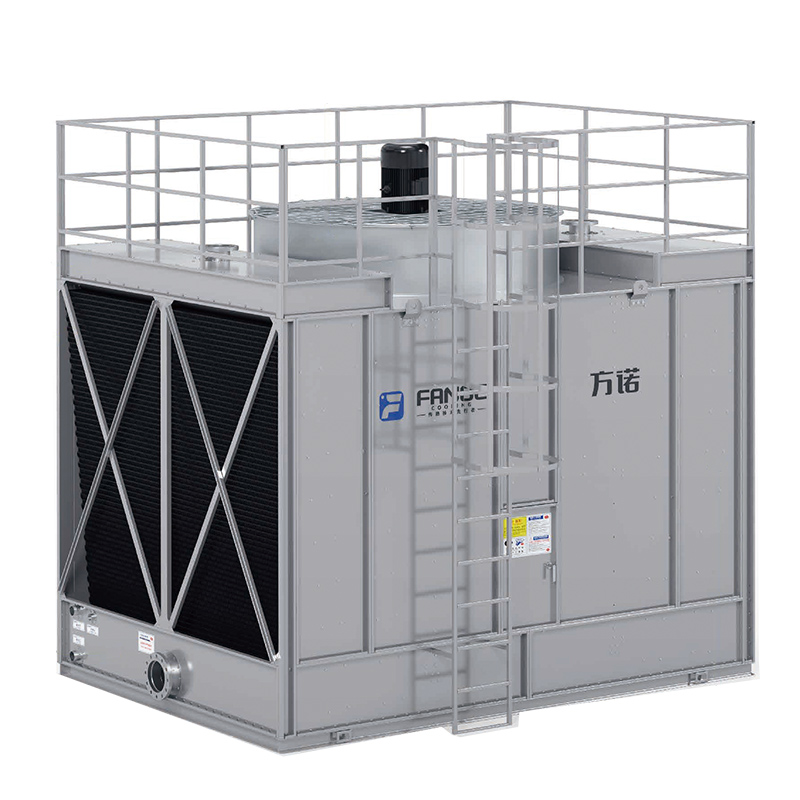 Cooling Towers Explained: How They Work, Types, and How to Pick the Right OneHow a Cooling Tower Actually Works A cooling tower is a heat rejection device that removes waste heat from a process or building system by transferrin...
 What Is an Open Circuit Cooling Tower and How Does It Work?An open circuit cooling tower is one of the most common and cost-effective solutions for industrial and commercial heat rejection. If you're evaluatin...